

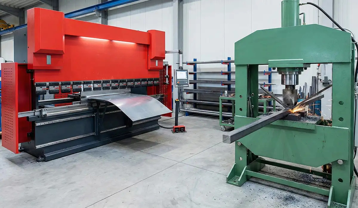
Press brake forming is a primary manufacturing process used to transform two-dimensional, flat sheet metal blanks into complex three-dimensional structural profiles. By applying targeted compressive and tensile forces along a straight bending axis, press brakes deform metal past its yield point into its plastic deformation regime, permanently altering its geometry without material removal.
From electronic enclosures and architectural panels to heavy chassis frames and agricultural equipment, precision bending requires a deep understanding of stress-strain mechanics, tooling setups, springback behavior, and bend allowance calculations.
1. Mechanics of Metal Bending: Stress and Strain Distributions
When a metal sheet is bent over a press brake die, a complex cross-sectional stress gradient develops across its thickness:
-
CROSS-SECTIONAL STRESS DISTRIBUTION IN A BEND
-
-
Compressive Stress Zone
-
Outside Radius ============================ (Tension)
-
/
-
/
-
——————–+—- NEUTRAL AXIS —-+——————–
-
/
-
Inside Radius ============================ (Compression)
-
Tensile Stress Zone
-
Outer Surface (Tensile Stress): Material along the outer bend radius is pulled outward in tension, undergoing elongation and localized wall thinning.
-
Inner Surface (Compressive Stress): Material along the inside bend radius is squeezed inward in compression, causing localized thickening.
-
Neutral Axis: Positioned between the tension and compression zones, the neutral axis represents the theoretical boundary where stress and strain are zero. As the bend progresses into the plastic deformation range, the neutral axis shifts inward toward the inside radius of the bend.
2. Fundamental Bending Methods
Sheet metal forming on a press brake relies on three primary process methodologies, differing in force requirements, precision, tooling contact, and springback characteristics:
-
+———————————–+
-
| PRESS BRAKE BENDING METHODS |
-
+—————–+—————–+
-
|
-
+—————————+—————————+
-
| | |
-
+—–+—–+ +—–+—–+ +—–+—–+
-
| Air Bending | | Bottoming | | Coining |
-
+———–+ +———–+ +———–+
-
• 3-point contact • Punch seats into die • Extreme tonnage penetrates
-
• Highly versatile • Reduces springback • Completely eliminates
-
• Lowest force requirement • Fixed bend angles • High tool wear
1. Air Bending
In air bending, the punch forces the sheet into the die cavity without pressing it completely against the bottom die walls. The metal contacts the tooling at only three points: the tip of the punch and the two upper shoulders of the V-die.
-
Advantages: Requires the lowest tonnage; a single set of tooling can produce various bend angles simply by adjusting the punch depth.
-
Disadvantages: Highly sensitive to material thickness variations and springback, requiring accurate CNC depth control.
2. Bottoming (Bottom Pressing)
In bottoming, the punch forces the sheet metal fully down until it makes complete physical contact with the angled walls of the V-die cavity. The applied force seats the material into the die angle (typically $88^circ$ or $90^circ$).
-
Advantages: Higher angular accuracy and consistency than air bending; significantly stabilizes springback.
-
Disadvantages: Requires 3 to 5 times more tonnage than air bending; requires dedicated tooling sets for each unique bend angle and thickness.
3. Coining
Coining uses extreme mechanical pressure—often 5 to 10 times the force of air bending—to drive the sharp tip of the punch directly into the metal substrate at the neutral axis. This action thins the material at the bend line and plastically deforms its internal grain structure.
-
Advantages: Completely eliminates springback and delivers exceptional angular precision.
-
Disadvantages: Extreme machine tonnage requirements, severe tool wear, and reduced fatigue life along the bend line.
3. Springback Mechanics and Mitigation Strategies
Springback is the unwanted partial recovery of a bent component toward its original flat shape upon the release of bending forces. It occurs because all metals possess an elastic limit; while the outer layers undergo permanent plastic deformation, the inner core retains residual elastic strain.
-
SPRINGBACK BEHAVIOR IN AIR BENDING
-
-
Punch Loaded (Under Force) Force Released (Springback)
-
-
| / /
-
| / /
-
|/ /
-
+—–+ +—–+
-
| | Angle $alpha$ | | Angle $alpha + Deltaalpha$
-
+—–+ +—–+
Factors Influencing Springback Magnitude
-
Yield Strength ($R_y$): Higher-strength materials (e.g., high-strength low-alloy steels, titanium) store more elastic energy, exhibiting substantially higher springback than soft aluminum or low-carbon steel.
-
Ratio of Bend Radius to Thickness ($R/T$): Larger bend radii relative to material thickness increase the volume of metal undergoing elastic deformation, leading to greater springback.
-
Bending Method: Air bending yields the highest springback, whereas bottoming reduces it and coining eliminates it entirely.
Springback Compensation Techniques
-
Over-Bending: Programming the CNC axis to bend the sheet past the target angle (e.g., bending to $87^circ$ so the material springs back to a precise $90^circ$).
-
Bottoming / Coining Setup: Converting the process setup to bottoming or coining to set the stress distribution at the bend radius.
-
Variable-Crown Bed Tables: Utilizing CNC-controlled dynamic crowning systems that compensate for structural deflection of the press brake frame under load, ensuring uniform angles across the full length of long parts.
4. Flat Pattern Calculations: Bend Allowance and K-Factor
To produce a finished part with accurate dimensional tolerances, engineers must calculate the exact initial flat sheet length before bending. Bending compresses the inner radius and stretches the outer radius, so calculating flat blank sizes depends on predicting the relocation of the neutral axis.
-
BEND REGION FLAT LENGTH VARIABLES
-
-
|<———– Bend Allowance (BA) ———–>|
-
___________ ___________
-
/
-
/
-
Inside Radius (R) /
-
_______________________________________/
-
|<————– Thickness (T) ———>|
K-Factor Definition
The K-Factor represents the ratio of the distance from the inside surface to the neutral axis ($t$) relative to the total material thickness ($T$):
$$text{K-Factor} = frac{t}{T}$$
-
For small bend radii ($R < T$), the K-Factor typically ranges between 0.30 and 0.40.
-
For standard air bending ($R approx T$), the K-Factor ranges between 0.42 and 0.48.
-
For large radii ($R gg T$), the K-Factor approaches 0.50.
Bend Allowance (BA) Formula
The Bend Allowance is the arc length along the neutral axis within the bend region:
$$text{BA} = frac{pi}{180} times A times left(R + (text{K-Factor} times T)right)$$
Where:
-
$A$ = Bend angle in degrees.
-
$R$ = Inside bend radius.
-
$T$ = Material thickness.
Bend Deduction (BD) and Setback (OSSB)
For direct CAD/CAM flat pattern layout, the Bend Deduction (BD) is subtracted from the sum of the outer flange leg lengths ($L_1 + L_2$):
$$text{Flat Blank Length} = L_1 + L_2 – text{BD}$$
Where Bend Deduction is derived using the Outside Setback (OSSB):
$$text{OSSB} = tanleft(frac{A}{2}right) times (R + T)$$
$$text{BD} = (2 times text{OSSB}) – text{BA}$$
5. Tooling Selection and Process Rules
Achieving precise bends and preventing equipment damage requires following fundamental process limits regarding V-die opening selection, minimum flange length, and minimum bend radii.
-
STANDARD V-DIE OPENING GEOMETRY
-
-
Punch Tip Radius (r)
-
|
-
V
-
/
-
/
-
___________/ ___________
-
| |
-
| / / |
-
| / V-Opening / |
-
| / <———–>/ |
-
| / |
-
+——————————-+
1. The 8x Thickness Rule for V-Die Selection
As a standard operational guideline for air bending low-carbon steel, the optimal V-die opening ($V$) is selected as eight times the sheet thickness ($T$):
$$V = 8 times T$$
-
V-Opening Too Narrow ($V < 6T$): Dramatically increases required tonnage, risks exceeding tool load limits, and causes severe surface marking.
-
V-Opening Too Wide ($V > 12T$): Produces inconsistent inside radii, increases springback, and broadens the minimum allowable flange length.
2. Minimum Flange Length Limitations
If a flange feature is too short, its edge will slip into the V-die opening before reaching the required forming depth, resulting in an inaccurate bend. The minimum safe flange length ($L_{text{min}}$) is generally calculated as:
$$L_{text{min}} approx 0.7 times V$$
3. Minimum Inside Bend Radius
Attempting to bend sheet metal to an excessively tight inside radius causes the material along the outer surface to exceed its ultimate tensile strength, leading to surface cracking and structural weakening. The minimum recommended inside bend radius depends on material ductility:
-
Ductile Aluminum & Soft Steel: $R_{text{min}} approx 0.5T text{ to } 1.0T$
-
High-Strength Alloy Steels: $R_{text{min}} approx 2.0T text{ to } 4.0T$
Summary
Press brake forming requires balancing stress-strain physics, tooling geometry, and material springback mechanics. By selecting appropriate bending methods (air bending, bottoming, or coining), utilizing exact K-Factor formulas for flat pattern development, adhering to V-die sizing rules, and compensating for elastic recovery, manufacturers consistently transform flat sheet metal into high-precision structural components.
Stainless steel pipes kampala uganda